| Measure DC and AC
voltage and current, resistance, and frequency
with TINA's Digital
Multimeter. You can use the multimeter in manual
or in autoranging mode. 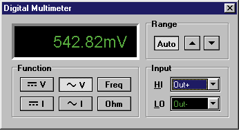
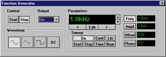
Function Generator
Generate sinusoidal, square, and triangular
waveforms at virtually any frequency. The
powerful sweep mode lets you choose start/stop
frequencies, step size, step time, and single or
continuous sweeps.
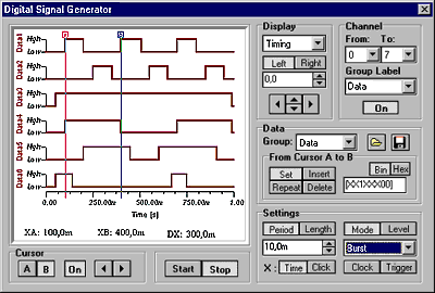
Digital Signal Generator
Use the Digital Signal Generator to create any
number of arbitrary digital signals to serve as
stimuli for your logic circuit. Setup timing
patterns effortlessly using the built in editor
with insert, repeat, and delete functions as well
as graphics cursor editing.
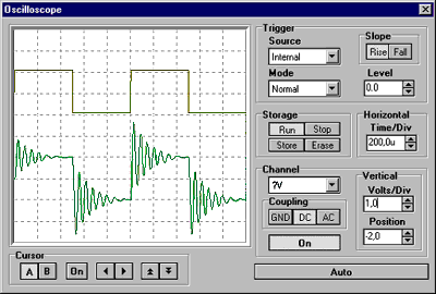
Storage Oscilloscope
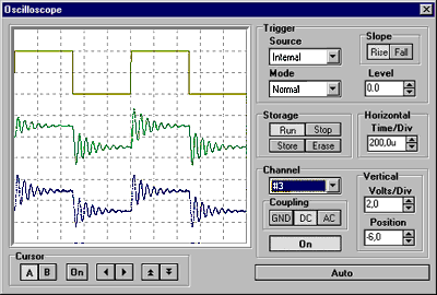
Display analog waveforms with TINA's
multichannel analog Storage Oscilloscope. You can
select external or internal triggering and a
variety of trigger modes. You can also move
graphics cursors to accurately measure voltage
and time.
Real-time Storage
Oscilloscope
Observe the actual time response of your
circuit. Set up the Function Generator for
waveform, amplitude, and frequency, drive the
testcircuit, and see the real-time response along
with the virtual response of the simulated
circuit.
Signal Analyzer
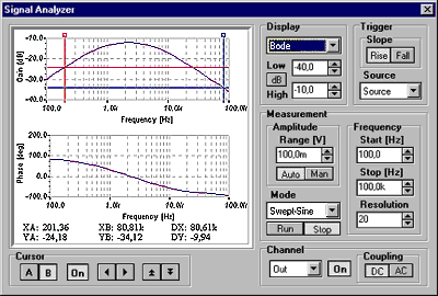
Working automatically in conjunction with the
Function Generator, the Signal Analyzer measures
and displays Bode amplitude and phase diagrams,
Nyquist diagrams, and more.
Real-time Signal Analyzer
Measure the frequency response of your circuit
in real-time. TINALab's
Function Generator will generate a real
swept-sine signal, capture the response, and
display it on the Signal Analyzer, where it can
be compared to the virtual (simulated)
measurements.

Logic Analyzer
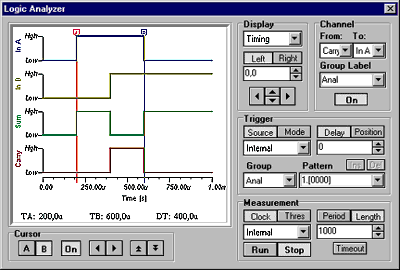
Debug your digital circuit with the advanced
Logic Analyzer. Select any number of channels and
arrange them into groups for easier viewing. You
can also define trigger patterns so that the
analyzer will capture a critical data segment.
Real-time Logic Analyzer
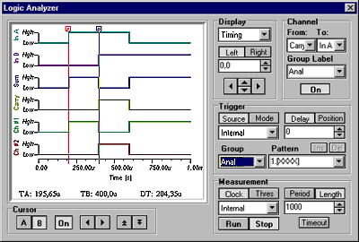
Set up the test stimulus for your logic
circuit with the Digital Signal Generator and see
eight channels of your circuit's real-time
digital response on the Logic Analyzer.
|
